Comparing KF, ISO and CF flanges

 by admin
There are numerous flanges in the world for all types of applications such as steam or liquids, but vacuum flanges have their own unique designs and designations.The most common vacuum flanges are the KF Flange, the ISO Flange and the CF Flange.
KF Flanges
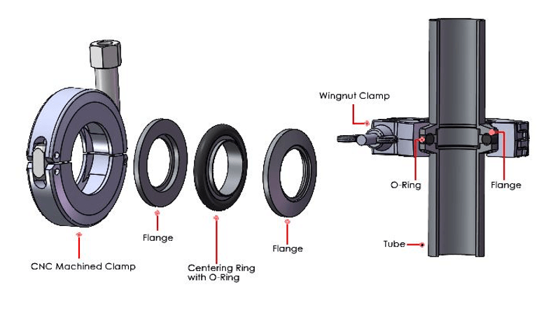
The word KF comes from the German Klein Flansche, translated into English as "little flange". These flanges have a 15 degree Angle (chamfer) on the back and are joined together by using tapered circular jigs. Manufactured according to DIN 28403/ISO 2861. They are also part of the Pneurop standard. These are asexual flanges, which means that the two sides of the connection are the same and there are no O-ring grooves in the flanges.
The flange size is based on the largest nominal I.D. tube, in millimeters, that can be welded to it. For example, the through hole of a KF25 flange is 25mm, or about one inch. In the U.S., it is common that the tubing that is welded to the flange is in a nominal inch size and it will be close, but not exactly the millimeter designation. Components manufactured outside of the U.S. will usually use tubing with a metric I.D.
Standard sizes are KF10, KF16, KF25, KF40 and KF50. Less common are the KF20 and KF32 sizes. There are several other names for this flange system, such as NW, QF, DIN, and ISO-KF, but all of these flanges are identical.
The principle of operation is this: a centering ring holding an O-ring is placed between the two flanges and then the flanges are aligned and brought close together. The wing nut clamp (chain clamps are also available) is placed around the two flange faces and the wing nut is tightened. The two flange faces are squeezed toward one another, thus compressing the O-ring.
These flanges are used in the pressure range from atmosphere to as low as 1×10⁻⁸Torr or mbar. The operating and bakeout temperature range depends upon the O-ring material. The most common O-ring material is FKM (Viton-A) which is suitable for the operating temperature range of 32 deg F to 356 deg F (0 to 180 deg C) and can be exposed to short-term temperatures in the range of -15 deg F to 400 deg F (-26 to 204 deg C). The leakage and permeability rate of these flanges with FKM is 1×10⁻⁹std cc/sec of Helium.
The most common material for these flanges is 304/304L stainless steel, but other materials such as 316L, 316LN and 6061 aluminum are also available.
ISO Flanges
Another metric flange that is larger than the KF flanges are the ISO flanges. Similar to the KF flanges they use a centering ring for sealing. They are manufactured according to the DIN 28404/ISO 1609 standard. They are also part of the Pneurop standard. These are sexless flanges; however, in some cases one of the two flanges will have tapped holes and then the two flanges will not be identical.
The flange size is based on the largest nominal I.D. tube, in millimeters, that can be welded to it. For example, the through hole of an ISO 100 flange is 100mm, or about four inches. In the U.S., it is common that the tubing that is welded to the flange is in a nominal inch size and it will be close, but not exactly the millimeter designation. Components manufactured outside of the U.S. will usually use tubing with a metric I.D.
Standard sizes are ISO 63, ISO 100, ISO 160, ISO 200, ISO 250, ISO 320, ISO 400, ISO 500, and ISO 630. Less common is the ISO 80 size. Although the ISO specification lists a maximum size of 630 mm, the same design principles are used to manufacture larger flanges. They are often (but incorrectly) referred to as ISO 800, ISO 1000, ISO 1250, and ISO 1320 sizes.
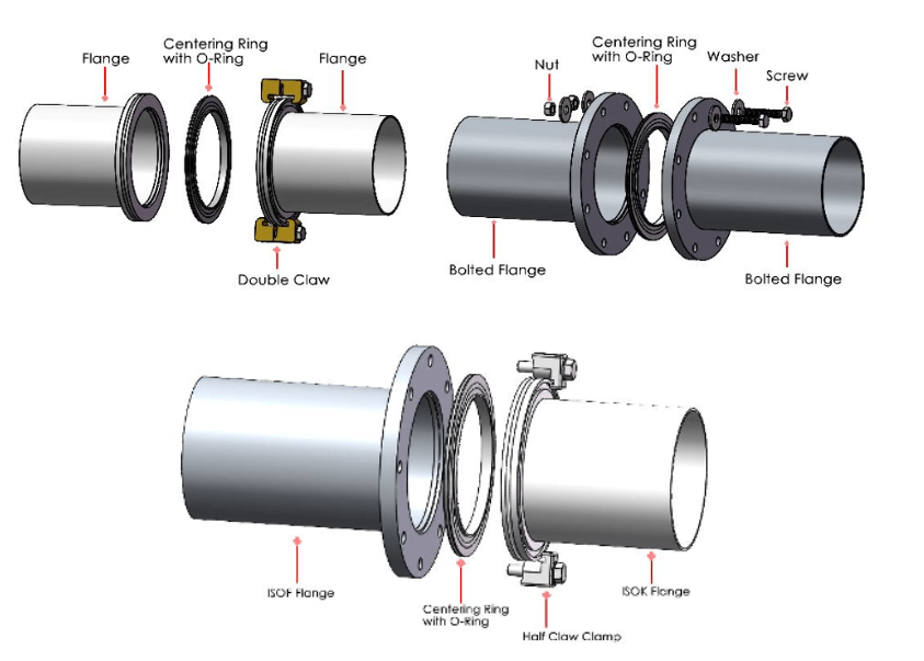
There are two different methods to join the flanges together: 1. Bolts (ISO-F) or 2. Claw clamps (ISO-K). These two flanges look very different, yet they can be joined together by using a half-claw clamp. The naming conventions can be a little bit confusing because the KF flanges above are often called ISO-KF flanges and the two types of larger ISO flanges are ISO-K and ISO-F.
This flange system is also known by several other names such as DIN XXX ISO (where XXX is the size designation), ISO LF (the same as ISO-K), ISO LFB (the same as ISO-F).
ISO-K flanges have a groove cut into the back of the flange so that a claw clamp can grab ahold of it. Because the letter “K” sounds the same as a “C” it can be helpful to remember that ISO-K requires a Claw Clamp.
ISO-F flanges have holes into the flange that can be used to bolt the two flanges together. These holes most commonly are through holes where a bolt is placed through both flanges; however, the holes can also be tapped where there is no access to place a nut (or nut ring) behind one of the flanges. It can be helpful to remember the ISO-F flange is flatand there is no groove for a claw clamp.
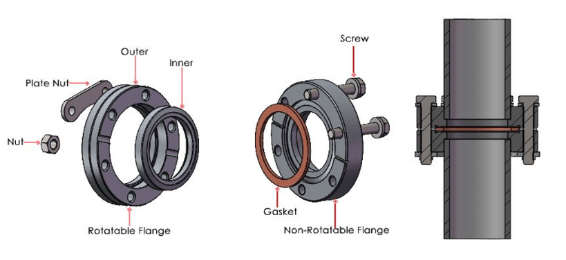
When two ISO-F flanges are bolted together the clocking of the bolt holes can affect the alignment and leveling of the two items that are joined by the flanges. For many flanged devices such as pumps and gauges the bolt-hole-pattern straddles the horizontal and vertical centerlines of the flanges. In other cases, the bolt holes will be oriented to be on the centerlines. To solve this, rotatable ISO flanges are available. In this case, the I.D. of the flange where the centering ring sits is fixed, and the bolt-hole-pattern is a second part that can rotate to any angle for perfect alignment. ISO-K flanges do not have this issue.
The principle of operation is this: A centering ring that holds an O-ring is placed between the two flanges and then the flanges are aligned and brought close together. The flanges are then joined by claw clamps (for and ISO-K), bolts (for and ISO-F) or with a half claw clamp (when joining an ISO-K to an ISO-F). In each case, as the bolts are tightened the centering ring is compressed making a leak-tight seal.
The operating specs are similar to the ISO-KF flanges. They can be used in the pressure range as low as 1×10⁻⁸Torr or mbar. The operating and bakeout temperature range depends upon the O-ring material. The most common O-ring material is FKM (Viton-A) which is suitable for the operating temperature range of 32 deg F to 356 deg F (0 to 180 deg C) and can be exposed to short-term temperatures in the range of -15 deg F to 400 deg F (-26 to 204 deg C). The leakage and permeability rate of these flanges with FKM is 1×10⁻⁹std cc/sec of Helium.
The most common material for these flanges is 304/304L stainless steel, but other materials such as 316L, 316LN and 6061 aluminum are also available.
CF Flanges
The term CF originally came from the name Conflat Flange. However, the word Conflat was a trademark of the Varian Corporation and the flanges became so popular that many companies are making them and using them. So, while they can be referred to as a conflat flange the shortened name CF is more widely used.
A CF flange uses a metal seal and is designed for higher vacuum applications where the permeability of an O-ring is significant to the gas load. Because all the parts are metal they can also be used when a bakeout is required at a higher temperature.
A helium molecule is 280 picometers in diameter (11 x 10-9inches). This molecule can migrate through all rubber compounds and will stream through all tiny holes. A mirror-like surface that looks perfect to the human eye is 0.02 to 0.05 RA micrometers at best. At 0.02 RA the helium molecule is 71 times smaller than the roughness of this surface. In comparison, the peaks and valleys in a mirror-like surface would look like skyscrapers from the perspective of a helium molecule. As explained below, CF Flanges are designed so no gasses can pass through the flanged joint, including helium which is used for leak testing.
Flange dimensions are usually specified by the outside diameter of the flange in inches. This is very different from KF and ISO flanges. The size of the commonly used have CF1.33, CF2.75, CF4.50, CF6.00, CF8.00, CF10.00, CF12.00, CF14.00 and CF16.50. Other less commonly used sizes are CF2.12, CF3.38, CF4.62, CF6.75, and CF13.25. These are made according to ISO standard ISO 3669-2. The decimal point is usually omitted in part numbers, so the actual external size of the CF275 is 2.75 inches. Bolt hole sizes (or threads, if the hole is a tap) are usually metric, but they also come in inch sized holes and inch threads.
These are sexless flanges, but for design purposes it is important to pay attention as to which holes are tapped and which are through, or the flanges may not bolt together.
The principle of operation is this: A knife edge is machined into both of the mating flanges. Then, a metal gasket made from a softer material (commonly copper) is placed between the two flanges. As the bolts are tightened, the knife edges cut into copper on both sides, making a leak-tight seal. Similar to the ISO Flanges, 2-piece rotatable CF Flanges are available. The pictorial below shows a rotatable flange on the left.
These flanges are used in the pressure range from atmosphere to as low as 1×10-12Torr or mbar, and the maximum bake out temperature is 842 degrees F (450 degrees C) with the standard copper gaskets.
The most common material for these flanges is 304/304L stainless steel, but other materials such as 316L and 316LN are also available. GNB also sells bimetal CF flanges. A typical application is to weld CF flanges with stainless steel knife edges to aluminum cavities.